foilassist.diy

As featured on the premier maker website, Thingiverse!
THE BLUEPRINT

THE FOIL ASSIST BLUEPRINT IS NOW AVAILABLE!
ON SALE FOR A LIMITED TIME!
$20
The Foil Assist Blueprint is my documented build journal. It is a 53-page, over-the-shoulder look at exactly how I took a pile of parts on my workbench and methodically put them together into a high-functioning foil assist unit.This isn't a generic textbook. It’s a highly detailed diary of my personal build process—the exact layout, settings, and wiring that allowed me to log more than 20 powered miles on foil. I spent the time making the mistakes, frying the wrong pins, burning out components, and figuring out what actually works so that you can see a proven roadmap before you ever pick up your tools.If you want to see the exact blueprint of a rig that not only works but actually performs, this is it!
What's Inside?
• My Chronological Build Log: A phase-by-phase record of my entire assembly process.• 53 Pages of Technical Notes: Clean, highly refined layouts and documentation.• 100+ High-Res Photos: Close-up workshop captures documenting every detail of my build.• My Wiring Schematics: The exact electrical maps and logical connections I designed.• ESC & Parameter Settings: The precise configuration data I programmed into my setup.• Tx / Rx Code Profiles: The exact code and custom transmitter throttle logic I loaded.• Battery Building: Cell selection, battery assembly, precautions, and charging.• Motor Mods & Upkeep: My physical modification steps and saltwater maintenance routines.• My 3D Print Settings: The exact temperatures and slicing profiles I used for my parts.• Lessons Learned: A transparent record of the pitfalls and headaches I avoided.
Page examples below.
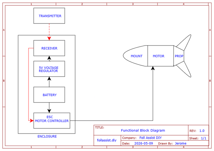
FUNCTIONAL BLOCK DIAGRAM
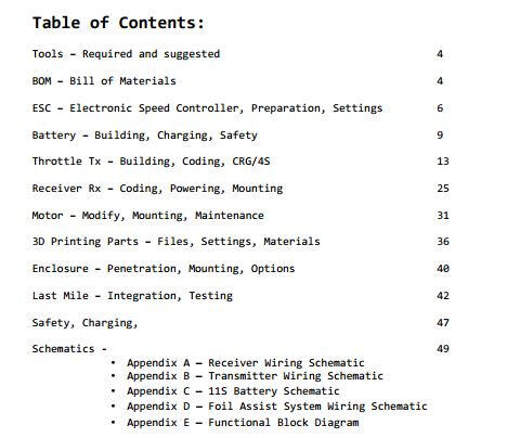
TABLE OF CONTENTS
Wiring
3D Printing
Motor Mods
The Enclosure


THE FOIL ASSIST BLUEPRINT IS NOW AVAILABLE!
ON SALE FOR A LIMITED TIME!
$20
Instant digital download — PDF format
Please respect the hundreds of hours that I spent designing, testing, and creating this guide. Please do not share or distribute it online.Thank you,
Jerome
Legal disclaimer: Builder assumes all responsibility for their build and its operation.
Note: I do not offer technical support — no email, no calls, no DMs, no exceptions.
Not because I don't like people. Because answering questions takes away from my other projects, riding my foil, and time with my family. I'm not willing to make that trade. Fair warning, fair deal.
I BUILT A Foil Assist for Under $300
Hello, my name is Jerome. My goal was to build a motorized foil assist unit for under $300 USD, and I did it! Now I want to share my experience and knowledge with anyone interested in doing the same.If you follow along, you will see exactly how I did it, what materials I used, how much they cost, where I got them, how I configured them, and how I assembled them. You can use this info as a blueprint for your build. You can modify it as you like, such as use a bigger 6384 motor, or a 65111 inrunner motor. You can use a 12S4P battery configuration for more range, or use a commercially available remote control with this build. You could even integrate the enclosure into your board! Use this information to inspire your build and guide you along the way.My BASIC BUILD JOURNAL is all here for FREE on the website. Just click on the buttons at the top and pick a topic. This online FREE BASIC BUILD JOURNAL is more comprehensive and complete than anything currently available online.
SUMMER IS HERE!
LET'S GO!
ON SALE FOR A LIMITED TIME!

Instant digital download — PDF format
$20
The FOIL ASSIST BLUEPRINT is NEXT LEVEL in scope and detail and is on sale for only $20. It has more details, close-up pictures, wiring schematics, maintenance tips, pitfalls to avoid, and a complete BOM with active product links! That alone will save you money -- by helping you avoid costly mistakes and wasted time. For most people, that easily covers the cost of the PDF!
PROVEN
Designing, creating, and testing my battery-powered foil assist rig was a crazy learning experience. After many failures and iterations, I was able to achieve success. Now you can skip all the failures and fast track your own foil assist build with all the information on my website. My build is reliable, repeatable, accessible and very budget friendly.I have logged over 20 miles of foiling on my rig, and I have only just begun. I have many, many more miles of wave riding to look forward to.


mission
I built this project to make foil assist accessible — simple, affordable, and open.
The challenge was to build a fully functional foil assist unit with a $300 budget. Someone on a forum said it could not be done. I proved it could.The success of this challenge is a big middle finger to the haters, the naysayers, and the gatekeepers who not only doubted this could be done, but discouraged others from daring to create, problem solve, and imagine. To those trolls and negative goons, I say stay in your box, the one that keeps you and others from progressing.This is my project documentation website. I have developed, compiled, and documented this information and it is available for everyone. All in one place. No more hunting through threads, searching endless websites, pricing multiple parts sources, or worse, finding incomplete or untrustworthy information.Simplicity at its core, only the essentials. That is my build philosophy. Complexity offers more failure modes. Sure, I could add all sorts of "features" such as a telemetry screen on the remote or a BMS. At worst, those are potential points of failure with added cost. At best, they are just conveniences. But the reality is that "features" do not enhance my ride, my foiling experience.This website is for all who dare to think outside the box and imagine what can be done.
BILL OF MATERIALS
Below is the Bill of Materials list with prices for every part used in my foil assist unit, everything down to the nuts and bolts, hook up wire, and even teflon tape. I ONLY used BRAND NEW PARTS! This is an extensive list and keep in mind that prices and availability can change. I have receipts for all of the items I used for this build. These are NOT estimates.
ESC Sequre SQESC 12200 $99.99
21700 Molicel P42A $2.65 each x33 $87.45
Nickel Strips 330mm x3 batteries $13.79/9754mm $1.40
XT60 Connectors $7.99/12 x 4 $2.66
Silicone Wire 12 Gauge $7.98/10ft x3ft $5.86
3D printed Cell holders $11.89/kg x84g $1.00
XT60 Splitters 12 Gauge $8.99/3 x2 $5.99
Silicone for Potting $19.99/64oz x4oz $1.26
6374 BLDC Motor $39.25
Rx ESP32 Wroom 1x $9.99/3 $3.33
Tx ESP32 S3 Supermini 1x $19.99/5 $3.99
3D printed Throttle Bracket $11.89/kg x58g $0.69
PVC 1 inch Riser Pipe $1.08
2x PVC threaded caps $2.68/each $5.36
Teflon tape $1.38/260" x36" $0.19
eBike Throttle Hall Sensor $6.49
Enclosure IP67 9x7x4 $9.99
Cable Gland IP67 3-Hole $2.33
3D printed Motor Mount $11.89/kg 96g $1.14
3D printed Propeller $11.89/kg 33g set $0.39
3D printed Propeller Hub $11.89/kg 54g $0.64
Mast Cable Guide $11.89/kg 26g $0.31
M4x45mm Cap Screw motor mount 0.22x4 $0.77
M4x45mm Cap Screw prop mount 0.22x2 $0.38
M4x8mm Cap Screw prop hub 0.03 x4 $0.12
M4 nylon lock nut prop mount 0.06 x2 $0.12
Velcro strap $8.99 /16' x2' $1.12
Enclosure Straps $7.99/4 $3.99
Floating wrist strap $11.99/4 $2.99
Tx Remote Battery LiPo 400mAh $9.99/4 x1 $2.50
JST-2.0 Battery cable $7.69/20 x1 $0.38
Silicone 22 Gauge wire $5.18/20 x1 $0.26
Buck/Boost 5V Voltage Regulator XL63020 $9.99/5 x1 $2.00
5V, Step-Down Voltage Regulator D45V5F5 $4.49
TOTAL COST $299.91

The entire BOM product links are listed on the premium PDF. It can save hours and hours of searching the internet. How much is an hour of time saved worth?
Note: The free information contained in this website is my build process. The premium PDF version adds build details, photos, temperature settings, pinout diagrams, tips, tricks, pitfalls, and product links. The PDF is my personal build journal which can be used as a blueprint to build your own. It is not a traditional "instruction manual". It is a very detailed account of how I took an overwhelming pile of parts and methodically assembled them into a high-functioning foil assist unit. My journal documents what worked for me. If it worked for me it can work for anyone. Obligatory legal disclaimer: The operation and safety of any build is the builder's responsibility.
ESC

ELECTRONIC SPEED CONTROLLER: I chose the Sequre SQESC 12200. I selected it for its impressive 200A current rating, its 5S to 12S battery capability, lightweight size, price, AM32 configurability, and easy setup. This is a good quality ESC and works well for this purpose. It even comes with heat shrink tubing for the terminal pads and a signal wire harness.This ESC is not VESC configurable. VESC is an awesome tool, but in my opinion it is incredibly overkill and complex for foil assist or eFoil use. It is like using an aerospace grade flight controller to operate a kitchen blender to make a margarita — totally unnecessary. For a foil assist, an ESC only has to spin a motor, one direction, with no brakes. That's it.
I started by tinning with solder the high-current solder pads on the bare SQESC 12200 board.
I pre-tinned then soldered 10 AWG silicone wire battery leads to the positive and negative pads, ensuring a solid, heat-saturated bond.
I pre-tinned and then soldered the three phase leads to the ESC pads marked A, B, and C.
I soldered the 4mm female bullet connectors to the ends of the three phase wires.
I soldered the XT60 male connector to the two power leads, being extra sure to maintain the correct polarity. I remembered to slip the shrink tubing onto the wire before making the solder connections.
After securely soldering the female bullet connectors and the XT60, I covered the exposed connections with heat shrink tubing.
To eliminate the risk of shorts, I covered the exposed copper and solder pads on the ESC with the heat shrink tubing that comes with the ESC.
I used a heat gun to shrink the tubing tightly over the pads and connectors for a clean, protected finish.
I soldered the signal wires to the ESC — white for signal, black for ground. The solder pads for the signal wires are between the ESC's power terminals.
Configuring the ESC was my next step. It is not difficult, but it is a bit technical. I used an AM32 configurable ESC, the Sequre SQESC 12200. AM32 is a program used to customize ESC settings.
I went to https://am32.ca/CONFIGURATOR and connected my ESC to my laptop via a USB cable and an AM32 linker adapter (I found one on Amazon for around $10).
I powered my ESC with a battery — 6S worked fine for configuration.
I connected my ESC to the am32.ca/CONFIGURATOR app.
My settings are shown in the picture below. After setting them, I saved them. I then clicked the "READ" button to confirm my settings had saved.
I gave the connections a final inspection to ensure the hardware was ready for the coming bench test.
My ESC is now assembled and configured.
The AM32 settings I used are shown below.

The complete itemized bill of materials for the entire build is on the BOM page.
BATTERIES

This component holds all the power — literally. There are many horror stories involving lithium-ion powered devices. Before I started my build, I had heard of exploding vape pens, cell phones, eBikes, hoverboards, and Teslas. I chose to treat the lithium-ion battery with respect, but I did not fear it. By being careful and knowledgeable of what I was doing, I was fine. I have not had any battery accidents. Knock on wood. What follows is exactly what I did to make my 11S3P 46.2V battery pack. With over 20 miles of successful riding, this battery building method has proven to be safe for me.
I ordered 33 Molicel P42A Li-Ion cells from 18650batterystore.com. They have sales periodically and I bought mine at a very low price of $2.65 per cell.
I graded each cell for capacity (mA), Internal Resistance (IR), and charged them to full voltage (4.2V). I used a XTAR VC8 charger.
I made sure all the specs were consistent and there were no significant deviations of low capacity, low voltage, or high Internal Resistance.
After grading my cells I divided them into 3 groups of 11 cells and hot glued them together, making sure the terminals were arranged in "series".
I used masking tape to number the terminals in the correct order, and to cover the exposed terminals to prevent accidental shorts while I was working on them.
I then spot welded nickel strips to the terminals. I was careful to ensure the nickel strips were welded to the terminals in "series".
After each strip is welded, I cover it with masking tape. This prevents accidental shorts while spot welding the other strips. You can't be too careful around these powerful cells, so use the utmost caution.
I took two 6-inch lengths of 12AWG silicone wire, one red and one black, and stripped the ends and tinned them with solder.
On one end of each wire, I soldered a female XT60 connector. On the other end of the pair of wires, I soldered a nickel strip. The nickel strip is the connection point to the negative end and the positive end of the 11S battery pack.
I carefully spot-welded the nickel strips to the battery terminal ends, being extra careful to get the polarity correct.
I then wrapped each pack in Kapton tape.
After removing the masking tape on the terminals, I place each battery pack in a 3D printed battery tray and prepared for silicone potting.
I mixed the 2-part neutral cure silicone and carefully poured it into the 3D printed battery holder/tray.
I made sure the terminals are completely covered with silicone.
I waited overnight for the silicone to cure, and then I repeated the steps on the other side of the battery packs.
I waited 24 hours for the silicone to fully cure.
With this modular battery concept, I made three 11S1P battery packs. The three packs will be connected by 12AWG splitter cables to make an 11S3P battery with a 12 Amp-hour capacity.
I opted not to use a BMS because I routinely monitor my discharge and charging and process. The BMS, in my opinion, is a battery nanny for people who don't know how or don't want to manage their battery. I bulk charge my battery/cells, and I have had ZERO issues or events. Educate yourself on battery management. Jehu Garcia on YouTube is an excellent resource for battery knowledge. https://www.youtube.com/@jehugarcia
My battery building process and charging process are detailed in the premium version PDF.


The complete itemized bill of materials for the entire build is on the BOM page.
TRANSMITTER / THROTTLE

REMOTE CONTROL: This is the transmitter unit. It’s designed to be rugged, easy to make, inexpensive, and completely waterproof. I used a 1" PVC riser as the body and a standard e-bike throttle for the controller. I chose this type of throttle because it uses a Hall effect sensor to send signals. This means the signal mechanism is immune to sand, saltwater, and corrosion. I completed the steps below and ended up with a throttle transmitter/remote control that I made from scratch. It works great, is very rugged, and was easy to build. If it works for me, it will work for you.Notes: I used PVC parts because they are very easy to source and they are completely waterproof, obviously. PVC should be available at every hardware store. The only variable might be the shape of the cap. It really depends on the manufacturer. But the 3D model is very simple, so it can be modified easily.I designed the throttle behavior specifically for foil assist and eFoiling. The code for the ESP32 module-controlled throttle is entirely my own creation. My concept is a response to the challenges of full-range throttle control. My concept is called Compressed Range Gearing with 4 Speeds (CRG/4S).How CRG/4S Works
Instead of using the entire throttle signal range, CRG/4S compresses the usable range into four distinct gears. This eliminates the need for the lower and upper extremes of the throttle signal, which are often either too slow or too aggressive for stable riding.For example:
The lower range of the throttle barely moves the propeller, so it’s excluded.
The upper range (e.g., 7854 RPM at full throttle, 46.2V x 170 KV) is unnecessary for most riding scenarios. By focusing only on the middle, usable range, CRG/4S provides precise control with four clearly defined speed settings.The 4 Distinct Gears of CRG/4S
Each gear is designed for a specific phase of eFoiling:Gear 1 – Slow Taxi
Ideal for getting the water moving under your hull.
Provides stability at low speeds.
Gear 2 – Planing Speed
A steady, stable speed to help you transition to kneeling or standing. The board is on plane
and very stable. Smooth speed without sudden lurches.
Gear 3 – Lift-Off Power
Designed for takeoff and cruising.
Doubles as the cruising speed—just set it and enjoy the ride.
Gear 4 – Boost Mode
A high-power boost for when you need extra speed or to escape tricky situations.
Also doubles as a cruise speed when the battery voltage sags.Why CRG/4S Solves the “Porpoising” Problem
When I first tried my friend Gary’s genuine Foil Drive, I loved the experience—but as a beginner, I struggled with hunting for the right RPM. It was either too fast or too slow and, I went up and down like a porpoise. The throttle felt like an on/off switch.
CRG/4S eliminates that porpoising—just direct, predictable control in every gear. Bonus: It gives you increased efficiency, extra runtime, and more fun!CRG/4S is Customizable and Open-Source. You can adjust the code to suit your weight or riding style. Feel free to tweak it and share it!
You can find the code below.
Have fun riding!
The complete itemized bill of materials for the entire build is on the BOM page.
Here is how I built my throttle:
I drilled a 5mm hole in the center of one PVC cap.
I inserted that cap into the 3D-printed throttle bracket, then slid the throttle into the bracket.
I routed the throttle signal cable through the hole in the cap.
For the seal: I used hot glue to secure the cable into the cap. I sealed both the inside and outside of the hole.
I applied Teflon tape to the riser threads.
I threaded the 6" riser into the bottom of the 3D printed throttle bracket and into the cap. That locked the cap, bracket, and riser into one solid unit.
I pulled the excess throttle cable out through the open end of the riser.
I stripped back the throttle cable jacket to expose the three wires — Red, Black, and Green.
Throttle to ESP32 S3 Supermini: I soldered Black to GND, Red to 3.3V, and Green (Signal) to Pin 4.
Power Regulation: Pin 1 (GND) to ESP32 GND
Pin 2 (Input) to the Positive of my battery pigtail
Pin 3 (Output) to ESP32 3.3V
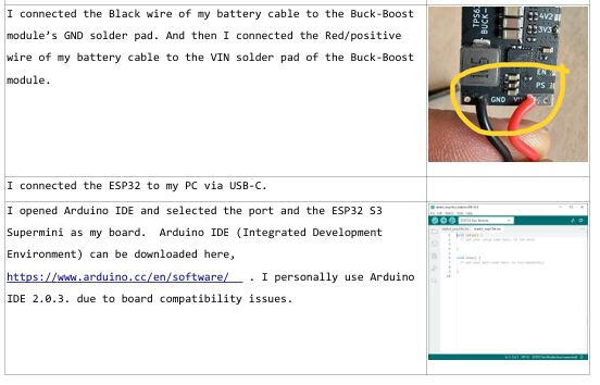
Battery Ground: I connected the Black wire of my battery pigtail to the ESP32 GND.
I connected the ESP32 to my PC via USB-C.
I opened Arduino IDE and selected ESP32 S3 Supermini as my board.
I copied and pasted the J-Drive Tx Sketch provided below.
I clicked Upload.
The test: I opened the Serial Monitor and pressed the throttle. When I saw the values changing smoothly, I knew my logic was live.
I protected the ESP32 with heat shrink tubing.
I drilled a small angled hole in the remaining PVC cap and threaded my wrist strap through it. I was careful not to drill into the inside of the cap, which would let water in.
I connected the LiPo battery.
I applied Teflon tape to the riser threads.
I carefully threaded the final cap onto the riser.
Since this was a proof of concept, it does not have an On/Off switch. To power on and off, I had to unscrew the bottom cap and connect or disconnect the battery terminal.
I have plans to add a small waterproof pushbutton switch for future versions.
The code for the ESP32 S3 based transmitter is provided below. My build journal PDF details how I upload the code to the ESP32 module.
#include <espnow.h>
#include <WiFi.h>
#include <espwifi.h>// =====================================================
// foilassist.diy
// CRG/4S ESP32 S3 SuperMini 4-Speed Discrete (Low Power Optimized)
// Tx Hall Throttle: Pin 4 | 920–2943 (12-bit, 3.3V)
// V260521 OPTIMIZED - PRODUCTION FIXED
// Output: 0–32767 CRG to RX
// =====================================================struct Packet {
uint16t throttle;
uint8t deadman;
};//============ REPLACE WITH YOUR SPECIFIC Rx MAC ADDRESS!!!! ========
uint8t rxMAC[] = {0xD4, 0xE9, 0xF4, 0x66, 0xBE, 0x7C};
espnowpeerinfot peerInfo;const int THROTTLEPIN = 4;// ---------- Throttle Calibration ----------
const int THRIDLESAFE = 910;
const int THRFULLSAFE = 2943;
const int THRFAULTLOW = 600;
const int THRFAULTHIGH = 3300;const float DEADZONE = 0.05f;// ---------- Gear Thresholds ----------
const float G2 = 0.05f + 0.2375f;
const float G3 = 0.05f + 0.2375f * 2;
const float G4 = 0.05f + 0.2375f * 3;// ---------- Discrete Gear Speeds ----------
const uint16t SPEEDG1 = (uint16t)(0.40f * 32767);
const uint16t SPEEDG2 = (uint16t)(0.60f * 32767);
const uint16t SPEEDG3 = (uint16t)(0.80f * 32767);
const uint16t SPEEDG4 = (uint16t)(0.95f * 32767);// ---------- Send Rate ----------
const unsigned long SENDINTERVALMS = 20;void setup() {
Serial.begin(115200);analogReadResolution(12);
analogSetAttenuation(ADC11db);
pinMode(THROTTLEPIN, INPUT);WiFi.mode(WIFISTA);// Minimum power setup
espwifisetmaxtxpower(0);
espwifisetps(WIFIPSMINMODEM);if (espnowinit() != ESPOK) return;memcpy(peerInfo.peeraddr, rxMAC, 6);
peerInfo.channel = 1;
peerInfo.encrypt = false;
espnowaddpeer(&peerInfo);
}void loop() {
int raw = analogRead(THROTTLEPIN);
uint16t crgOut = 0;// ---------- FAULT CHECK ----------
if (raw < THRFAULTLOW || raw > THRFAULTHIGH) {
Packet pkt = {0, 1};
espnowsend(rxMAC, (uint8t *)&pkt, sizeof(pkt));
}
else {
// ---------- NORMALIZE & CALCULATE ----------
float norm = (float)(raw - THRIDLESAFE) / (float)(THRFULLSAFE - THRIDLESAFE);
norm = constrain(norm, 0.0f, 1.0f);if (norm < DEADZONE) {
Packet pkt = {0, 1};
espnowsend(rxMAC, (uint8t *)&pkt, sizeof(pkt));
}
else {
// ---------- GEAR SELECTION ----------
if (norm < G2) crgOut = SPEEDG1;
else if (norm < G3) crgOut = SPEEDG2;
else if (norm < G4) crgOut = SPEEDG3;
else crgOut = SPEEDG4;Packet pkt = {crgOut, 1};
espnowsend(rxMAC, (uint8t *)&pkt, sizeof(pkt));
}
}Serial.printf("RAW:%4d | CRG:%5d
", raw, crgOut);// THE FIXED TIMING: Let the background task flush the radio buffer cleanly
vTaskDelay(pdMSTOTICKS(2));// Safely drop into Light Sleep without locking up the S3 registers
espsleepenabletimerwakeup(SENDINTERVALMS * 1000);
esplightsleep_start();
}
RECEIVER

The receiver is the connection between your finger and the propeller. Its primary job is to receive the throttle signal from the transmitter and translate that signal and feed it to the ESC (motor controller).I selected the ESP32 development modules for my remote control system. The advantage to using this particular microcontroller is that it has a native radio on board, therefore it has Tx and Rx capability built in. It uses ESP NOW communication protocol.Why should anyone care? Because it has no latency, and it pairs instantly. What does that mean? It has no lag time and instant throttle response! And, it is easy to configure.Below, I outline the steps I used to prepare the receiver.
Power Regulation is provided by the Step-Down Voltage Regulator D45V5F5:
I soldered a 6-inch length of black 22AWG to the GND pin on the step-down voltage regulator and the other end to the ESP32 GND pin.
VIN (Input) wired to the Positive of the battery cable.
VOUT (Output) is wired to ESP32 pin V5
Battery Ground: I connected the Black wire of the battery cable to the ESP32 GND pin.
To upload the code the ESP32 WROOM, I connected it to my PC via a USB-C cable.
I opened the Arduino IDE and selected "ESP32 Dev Module" as my board and chose the listed COM port.
I copied and pasted the J-Drive Rx Sketch (provided below) into the Arduino IDE.
I clicked "Compile and Upload" and waited.
The test: I opened the Serial Monitor and pressed the throttle. When I saw the values changing smoothly, I knew my logic was live.
I covered the ESP32 with heat shrink tubing to protect it from shorts.
This stage was done.
The code for the ESP32 receiver is provided below. My build journal PDF details how I upload the code to the ESP32 module.
#include <espnow.h>
#include <WiFi.h>// =====================================================
// foilassist.diy
// LEDC RX WITH GEAR HYSTERESIS
// V260516 Website Rx
// =====================================================struct Packet {
uint16t throttle;
uint8t deadman;
};volatile Packet incoming;const int OUT1 = 18;
const int PWMMIN = 1000;
const int PWMMAX = 2000;
const uint16t RXMAX = 32767;
const unsigned long RXTIMEOUTMS = 500;// LEDC config
const int LEDCCHAN = 0;
const int LEDCFREQ = 50;
const int LEDCRES = 16;// Hysteresis threshold (prevents gear hunting)
const uint16t HYSTERESIS = 800;// Full throttle lock release threshold
const uint16t FULLRELEASE = 2000;unsigned long lastRxTime = 0;
bool armed = false;
bool linked = false;
bool fullThrottleLock = false;
uint16t lastCrg = 0;void setPulse(int pulseUs) {
uint32t duty = pulseUs * 3.27675; // 65535 / 20000us
ledcWrite(LEDCCHAN, duty);
}void writeIdle() { setPulse(PWMMIN); }void disarm() {
if (armed) {
Serial.println("DISARMED");
armed = false;
}
fullThrottleLock = false;
writeIdle();
}void onReceive(const uint8t *mac, const uint8t data, int len) {
if (len == sizeof(Packet)) {
memcpy((void)&incoming, data, sizeof(Packet));
lastRxTime = millis();
linked = true;
}
}void setup() {
Serial.begin(115200);ledcSetup(LEDCCHAN, LEDCFREQ, LEDCRES);
ledcAttachPin(OUT1, LEDCCHAN);
setPulse(PWMMIN);WiFi.mode(WIFISTA);
espnowinit();
espnowregisterrecvcb(onReceive);
Serial.println("RX ONLINE");
}void loop() {
if (!linked) return;// Failsafe
if (millis() - lastRxTime > RXTIMEOUTMS || incoming.deadman == 0) {
disarm();
return;
}// Arm on zero throttle
if (!armed) {
if (incoming.deadman == 1 && incoming.throttle == 0) {
armed = true;
fullThrottleLock = false;
Serial.println("ARMED");
} else {
writeIdle();
return;
}
}// Throttle processing
uint16t crg = incoming.throttle;
if (crg > RXMAX) crg = RXMAX;// Apply hysteresis (prevents gear hunting)
if (abs((int)crg - (int)lastCrg) < HYSTERESIS && crg != RXMAX) {
crg = lastCrg;
}
lastCrg = crg;// Full throttle lock
if (crg == RXMAX) fullThrottleLock = true;
if (fullThrottleLock && crg < (RXMAX - FULLRELEASE)) fullThrottleLock = false;
if (fullThrottleLock) crg = RXMAX;// Output to ESC
int pulse = map(crg, 0, RXMAX, PWMMIN, PWMMAX);
setPulse(pulse);
}
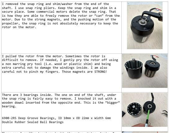
MOTOR

The ubiquitous 6374 BLDC motor provides the thrust for this build. It is the standard size motor that many commercial foil assists use. They are readily available and relatively inexpensive, around $40. They are so inexpensive that I could buy 17 of them for the price of a commercial replacement (~$700). So hypothetically, I could buy a new motor each season, for 17 seasons, for the price of one commercial motor. In other words, I don't sweat it if it craps out after good use. But, I address the topic of maintenance and bearing replacement in the premium PDF.
6374 BLDC motors come with a long shaft that will need to be shortened. The shaft interferes with the mounting to the foil mast. It is not difficult to modify. Follow the steps below.
First thing is to make a jig to hold the motor. I found a thin but stiff metal plate and drilled mounting holes in it to mount the motor. I also drilled a hole for the shaft to protrude through.
I secured the metal plate in a vice. This will be my jig.
I mounted the motor to it using two M4 screws. I was careful not to screw too far in and damage the windings inside.
I put the motor in a plastic bag to prevent the shavings from entering the motor magnets.
I pushed the excess shaft through the plastic bag.
I secured the motor in the jig.
I measured and marked where I wanted to cut the shaft.
I cut the shaft using an angle grinder with a thin cutoff wheel.
I deburred and sanded the cut edge smooth. It is a good idea to round off the cut end for reasons I discuss in the motor maintenance section of the premium PDF.
I removed the motor from the jig and removed the plastic cover.
The motor is ready to be mounted.
3D PARTS

3D printed parts are satisfying and relatively easy to make! I use a stock Creality Ender3 printer. You can pick them up on Facebook Marketplace for around $50 used. Once I got my bed leveled and set up, it worked fine. Also, Ender3 parts are super cheap and readily available.
The great thing about having a 3D printer is that you can make unlimited spare parts (extremely inexpensive) and modifications.I use PLA filament. Haters will say PLA doesn't work for propellers. They will say, "What about the UV exposure"? Keep your parts out of the sun when not in use. They will say, "You have to use Nylon or CF (carbon fiber) reinforced filaments!" Nylon is flexible and less rigid than PLA, and CF-PLA may be overkill. They will tell you that you can't do this and you can't do that.Some people will say you need to coat your parts in epoxy, and you need to fine-tune and balance your prop blades. I didn't, and my parts are working fine! I ride mine all the time, zero issues with excessive vibration or out-of-balance blades or separating layers.In fact, I have only had 2 parts fail during this whole process, and both were my fault, not the fault of PLA filament.
Failure 1: The propeller blade snapped off at its base. The cause was incorrect print orientation. I stupidly printed the blade in a vertical orientation, and the layers were in a concentric pattern. Of course it would snap off! Duh. Print orientation is IMO the most important factor in making a strong and reliable part.
Failure 2: I had been post-session rinsing my motor with fresh water (totally fine) and finishing with a spray of WD-40. The WD-40 spray got on the propellers and weakened the PLA; they eventually failed. My fault again. DO NOT USE WD-40 ON PLA. I only use Corrosion-X on my motors now. It doesn't seem to affect the PLA, or it hasn't yet (it's been months). To date, I have over 20 miles of riding on PLA propellers with ZERO FAILURES!I ignore the haters, naysayers, and gatekeepers because I'm too busy foiling.
1. Download the STL Files
- I found the STL motor mount and propeller files online at Thingiverse.com and downloaded them to my computer. Where necessary, I modified them to fit my needs. I have provided the Thingiverse links at the end of this page.2. Prepare the File in Slicer Software
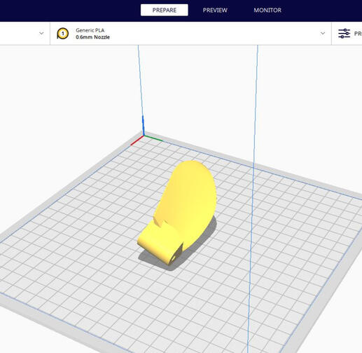
- I opened the STL file in my slicer. I use Cura as my slicer.
- I positioned the part on the virtual build plate to optimize print strength and quality.
The most critical factor IMO regarding the part's strength is print orientation.*
- I adjusted settings like:
- Layer height I used 0.3mm for faster printing and strength.
- Infill density I used 100% for strength.
- Supports (enabled if the part has overhangs).
- Print speed (slower for better quality, faster for prototyping).
- I sliced the file to generate the G-code.3. Prepare the 3D Printer
- I cleaned the build plate to ensure the part would stick properly.4. Start the Print
- I transferred the G-code file to the printer via SD card or USB.
- I started the print and monitored it for the first few layers to ensure it adhered correctly.5. Post-Print Finishing
- Once the print finished, I carefully detached the part from the build plate.
- I removed any supports with pliers or a knife.
- I sanded rough edges if needed for a smoother finish.6. Final Checks
- I inspected the part for any defects or issues. If they look good then they are ready to install.
Cura Slicer settings and other detailed tips are provided in the premium PDF.
Links to free 3D part files are provided below.


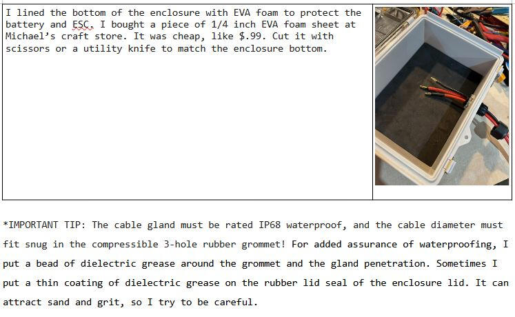
enclosure

I used an IP67 rated enclosure for this build. I have tried all sorts of enclosures, such as handgun cases, hinged and unhinged electronics enclosures, aluminum, and plastic. I even tried an ammo box. The most important thing to consider is that the enclosure must be rated IP67 waterproof or better. Secondary is size. Of course, I tried to keep it small and light. There is always room for improvement. This enclosure is what I used for this version. It works very well. No issues. I only needed to make one penetration for the phase wires. The steps below document how I did it.Of course, I don't prefer to have a goofy box sitting on the deck of my board, but future solutions are coming. For now, the will to ride is stronger than my dislike of a deck mounted box.
I used my cordless drill with a step drill bit and, I drilled a clean hole in the enclosure wall.
I was careful not to drill too large of a hole, just big enough for the gland's threaded diameter.
Placement is important. Not too close to where I thought the batteries or ESC might be. There has to be some clearance for the incoming cables.
I slid the gland’s gasket ring on and pushed the gland through the hole from the outside.
Inside, I screwed the gland’s nut hand tight to lock the cable in place.
The cable gland I used has a 3-hole pattern, perfect for the 3 phase wires of the motor.
I lined the bottom of the enclosure with EVA foam to protect the battery and ESC.
*IMPORTANT TIP: The cable gland must be rated IP68 waterproof!
ASSEMBLY

Almost finished and so close to ride time!
I Installed the batteries, the Receiver, and the ESC in the enclosure. Tried to give the ESC as much air space as possible, to keep it cool. I kept it from contacting the batteries directly.
I connected the receiver wires to the ESC.
I installed the motor mast mount to the motor.
I then installed the motor mast mount onto the mast. I mounted mine about 8-10 inches from the bottom of the board.
I fed the motor phase wires from the motor in through the 3-hole cable gland that was installed earlier. Depending on the size of your board and the placement of your enclosure, you will likely have to make a 3 wire extension from the motor to inside the enclosure.
Inside the enclosure, I connected the motor phase wires to the ESC.
I mounted the propeller hub to the motor.
I installed the propeller blades to the propeller hub.
I connected the LiPo battery in the throttle Tx. I check for the "On" LED on the ESP32 S3 Supermini board.
I connect the battery to the ESC. This caused a spark and a pop. This was due to the bulk capacitors on the ESC. I wasn't alarmed; this is normal.
I listened for the motor to beep, it was looking for the Tx signal.
The motor stopped beeping after it found the signal.
My system was now armed and ready.
I pull the throttle trigger in gradually. The motor spun through all 4 gears of the CRG/4S.
Success!
PICTURES

COMING SOON!
SOAPBOX
COMING SOON!

COMING SOON!
skunkworks

COMING SOON!
TENTATIVE SKUNKWORKS RELEASE SCHEDULE:
SUB $300 J-DRIVE STANDARD 5/21/2026
SUB $400 eFOIL J-FOIL 7/7/2026
SUB $350 J-DRIVE DAILY DRIVER TBD
J-DRIVE PASSPORT FOIL ASSIST TBD
SUB $250 J-DRIVE LIGHT TBD
TWIN-TURBO 5065 TBD
J-DRIVE MICRO BOOST TBD
J-DRIVE TOW-BOT™ TBD
$20
Instant digital download — PDF format